How to Construct a Golf Simulator Frame and Mount the Screen (Part 2)
08 Aug 2024
by Jay Hubbard of Ace Indoor Golf
see also: Equipment Reviews
SHARE:
Golf Simulator Components
Ready to set up a DIY golf simulator at home but unsure where to begin? No need to fret! This detailed guide will show you how to build a strong frame for your simulator and attach a screen, step by step. With these instructions, you'll soon enjoy a high-quality golfing experience from the comfort of your home. This is the second article in a series of three. The first feature explained how to measure for your golf simulator screen and pads. In this article, we'll cover the construction of the simulator frame and screen attachment. The final installment will walk you through building the golf simulator enclosure.
RELATED: Creating Your Golf Simulator: Accurate Measurement and Setup Tips (Part 1)
RELATED: How to build a golf simulator enclosure (part 3)
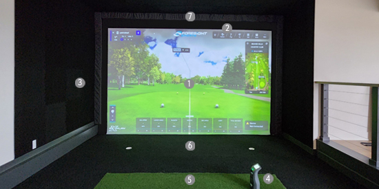
To get started, it's important to familiarize yourself with some essential terms. A golf simulator setup typically includes a screen (1), an enclosure (2), a launch monitor (3), a hitting mat (4), gap pads that fill the space between the screen and the frame (5), frame pads to safeguard both the frame and the golfer from ricochets (6), as well as the simulator frame and projector (not shown here).

Measuring for Your Golf Simulator Frame:
- Start by measuring the space between the adjacent walls to get precise dimensions for your screen frame.
- Identify and account for any obstacles such as light fixtures, vents, or electrical outlets that could influence where the screen or frame should go.
- Factor in the room’s height and the preferred viewing angle to determine the best position for the screen.
- Verify all measurements carefully to ensure they are correct before proceeding with cutting or installation.
- Use a level to check that the frame is perfectly aligned with the walls and ceiling for a straight and even setup.
- Allow extra space around the frame to accommodate any protruding elements or trim.
- Keep potential future upgrades or modifications in mind, as they could affect the frame’s placement or size.
Many leading simulator retailers recommend using Electrical Metal Tubing (EMT) or Polyvinyl Chloride (PVC) pipes for constructing your golf simulator frame. At Ace Indoor Golf, we disagree with this recommendation. Metal pipes are prone to dents, offering poor stability and posing a risk of dangerous ricochets. Similarly, PVC pipes can crack and break, potentially sending sharp plastic shards flying. Additionally, using pipes makes it challenging to attach the screen and padding, and even harder to make adjustments. At aceindoorgolf.com, a major manufacturer and retailer of golf simulators, we advise using 2x4 lumber for constructing your frame. This approach ensures a sturdy, stable, and long-lasting frame that will serve you well for a lifetime.
Needed Parts
Additional Parts Depending on Wall And Ceiling Configuration:
Tools
- Hammer Drill
- Shop Vac
- Hammer
- ¼” Concrete Drill Bit
- Wire Brush
- 5/16” screwdriver bit
- 3’ or 4’ Level
- 25’ Tape Measure
- Chalk Line
- Hand Held Carpet Seam Rolling Tool
- 48” Aluminum Straight Edge for CuttingBox cutters and blades
Building A Golf Simulator Frame Cutaway Parts

Fabricating A Frame for Your Golf Simulator
Are you eager to create your dream DIY golf simulator. This guide will take you through the process of constructing a golf simulator frame and attaching the screen. This is the second installment in our three-part series:
- Article One: Covers accurate measurements for your golf simulator screen and pads.
- This Article: Provides detailed instructions for building the frame and attaching the screen.
- Article Three: Focuses on constructing a golf simulator enclosure to complete your setup.
Attaching and Supporting the Frame
To ensure stability, the frame holding your golf simulator screen, which can endure impact speeds of up to 220 MPH, must be securely anchored. Depending on your space, you may need to anchor the frame to the floor, side walls, and ceiling. If some of these options are unavailable, you can still stabilize the frame by anchoring it to the floor and rear wall. Below are instructions for each attachment method:
- Attaching a frame to side walls and the ceiling
- Attaching a frame to the ceiling and floor
- Attaching a frame to two side walls (No ceiling)
- Attaching a frame to the floor and rear wall only
Here’s how you can construct a 2x4 frame and secure it to the ceiling, floor, side walls, or back wall with these easy-to-follow steps.
1. Possibility One: Attaching The Frame To Side Walls And The Ceiling

- To reduce the risk of damage from ball collisions, position the screen frame at a distance of 10 to 12 inches from the back wall. Mark a 12-inch measurement from the rear wall along both side walls at both the floor and ceiling levels.
- Measure the height from the floor to the ceiling on each side wall, subtracting 1.5 inches to account for the Top 2x4 that will be anchored to the ceiling. Cut the side frames according to your measurements and place them at the designated 12-inch mark from the rear wall. Ensure the 2x4s are level and secure them to the side wall using either 5/16” x 4” structural screws or 5/16” x 4” x 1/4” toggle bolts, spaced every 12 to 16 inches.
- Determine the ceiling width between the two side frames and cut a 2x4 for the top frame. Position the 2x4 so it rests across the two side frames, gently tapping it in with a hammer if necessary. Fasten the Top frame to the ceiling with 5/16” x 4” structural screws or 5/16” x 4” x 1/4” toggle bolts (if studs are not available) at intervals of 12 to 16 inches.
2. Possibility Two: Attaching The Frame In The Ceiling And Floor

- On each side wall at the ceiling, measure 12 inches from the back wall and make a mark. Then, use a chalk line to connect these marks across the ceiling.
- Measure the overall length of the room, then cut a 2x4 to fit for the top frame. Attach the 2x4 to the ceiling along the chalk line, ensuring it maintains a 12-inch gap from the back wall. Use 5/16” x 4” structural screws or 5/16” x 3” x 1/4” toggle bolts to screw the frame into the ceiling, placing them every 16 inches.
- For the side frames, measure from the floor to each end of the top frame and cut a 2x4 according to those measurements. Position the side frame pieces underneath the top frame so that the outer edges are flush. You may need to lightly tap them into place with a hammer. To connect the top and side frames, take a 2” double-wide mending plate and secure it at the top outer edge of both the frames using 1” x 5/16” screws. Repeat for the opposite side. Alternatively, you can attach a 2” zinc L-Bracket flush against the inside of the top and side frames using 1” x 1/4” screws. Ensure the L-Bracket is positioned to accommodate the angle irons that will connect to the front of the entire frame.
- Now position an 2” L-Bracket at the inside edge of each side frame on the floor. Use a pencil to mark where the holes in the L-Bracket touch the concrete floor and side frame.
- With a 1/4” concrete drill bit, wrap tape around the bit at a distance of 3 inches from the tip to indicate your drill depth. Use a hammer drill set to hammer mode to create two 3” deep holes in the marked spots on the concrete floor.
- Clear away any debris using a vacuum and wire brush, then thread a 3” Tapcon flat head concrete screw through the 2” L-Bracket and carefully screw it into the concrete. Ensure the screw is not driven too quickly to avoid stripping the base material. Avoid over-tightening. Repeat this step on the other side.
- Insert 1” x 5/16” roofing screws into the holes of the L-Bracket on each side frame to secure them.
Option 3: Attaching The Frame In One Or Two Side Walls And The Floor

- To reduce the risk of damage from ball impacts, position the screen frame 10 to 12 inches away from the rear wall. Make a mark 12 inches from the rear wall on both the floor and ceiling of the wall(s).
- Refer to the measuring guidelines from the first article to determine the distance from the floor to the ceiling on the side wall(s). Cut the side frames according to these measurements and position them at your marked points, maintaining a distance of 12 inches from the rear wall. Ensure the 2x4s are level, and secure them to the side wall using 5/16” x 4” structural screws or 5/16” x 4” x 1/4” toggle bolts, spacing the fasteners every 12 to 16 inches. If you only have one side wall for anchoring the frame, refer to Option 2 in steps 4-8 to secure the side frame without a wall.
- Position the top frame on top of the side frames, aligning the outer edges to be flush. Fasten the top frame to the side frame with two 5/16” x 4” structural screws.
- Although not depicted in the previous photo, the top frame should also be secured to the rear wall using five or six 12” 2x4 supports—one at each end top and bottom and one in the top center. Measure and cut five Support 2x4s and place them between the top frame and the rear wall. Use two 5/16” x 5” screws to attach the Support 2x4s to the front of the top frame. Install a 10” heavy-duty L-Bracket beneath each Support 2x4, securing it to the wall with 5/16” x 3” screws or toggle bolts. Finally, attach 1” x 1/4” screws to connect the L-Bracket and the Support 2x4. Repeat this process for the middle and the other side frame.
4. Option 4: Attaching The Frame In The Floor and Rear Wall Only
To reduce the risk of damage from ball impacts, position the screen frame 10 to 12 inches from the back wall.
- Mark the locations for the two side frames by measuring 12 inches from the rear wall along the floor. Next, refer to the dimensions provided by the Aspect calculator (see the article on Measuring for Your Golf Simulator Screen and Frame Pads) to determine the width and height. Cut a 2x4 for the top frame and the two side frames based on these measurements. Assemble the side frames and the top frame on the ground, ensuring that the outer top edges are flush. Secure them together by driving two 5/16 x 4” structural screws into the ends of the top frame and into the top of each side frame. Additionally, cut five or six 12” long support 2x4s to secure the simulator frame to the back wall. Put one support on the top and bottom of each side, and one or two for attaching the middle of the top frame to the rear wall.
- With the help of two people, raise the frame into position while a third person places a 12” support 2x4 between the frame and the rear wall at the outer edges and in the center. Screw two 5/16” x 5” screws through the front top frame and into each support 2x4s. Attach a 10” heavy-duty L-bracket underneath the top support 2x4s, and secure it to the wall using 5/16” x 3” screws or toggle bolts. Repeat this process for all the top support 2x4s.
- For the side frames, follow Possibility 2 steps 4 through 8 to anchor them to the floor.
- At this point, the frame should be securely anchored in place.
B. SCREW ANGLE IRONS INTO FRAME
- Attach the Steel Slotted Angle irons to the front, interior edge of the frame. Fasten the Angle irons around the entire frame by screwing them into the studs using 1” x 5/16” roofing screws with a rubber washer placed every 12 inches. (Refer to the two Angle Iron images below.)


- Remove the backing from the Sticky Hook Velcro and apply it to the entire front surface of the 2x4 frame. (Refer to the image below.)

- Install 1” x 5/16” roofing screws equipped with rubber washers into the Velcro positioned every 12 inches around the frame to firmly secure it in place. The Hook Velcro will be utilized to fasten Ace Carpet/Gap pads to both the frame and the screen, effectively (See picture below)

- At this stage in the process, we suggest constructing your enclosure by either installing golf simulator curtains or attaching golf simulator tiles to your wall(s). Completing this step will help safeguard your screen from dirt and damage during the installation process. For more information, refer to Article Three on Building a Golf Simulator Enclosure.
C. HANGING THE SIMULATOR SCREEN
- The bottom of the screen features a pocket. First, lay the Shock Cord pocket flat on the ground, centered between the frame. Place one leg of the ladder on top of the Shock Cord pocket. Start by hanging the top corners of the screen, loosely threading cable ties through the corner grommets. Do not tighten them yet.
- Next, loosely thread additional cable ties through the grommets along the top of the screen, keeping the ladder positioned on top of the Shock Cord pocket while ensuring the screen remains level and centered within the frame.
- Secure the bottom corners tightly with cable ties.
- Finally, tighten the top cable ties so that the screen hangs vertically, centered, and level with the top edge.

- 5. Fasten the screen sides to the frame by threading 10” long stretch cords with a diameter of 3/16” through the screen grommets and securing them onto the Angle Iron slots. Make sure to adjust the screen so it is centered and snug, but avoid over-tightening, as this may cause the screen to act like a trampoline for the golf ball. (Refer to the picture below.)

- 6. Install a ¾” x 1 1/2” eyelet into the front of each side frame, positioning it as close to the ground as possible. This will allow you to attach the shock cord to each side of the frame. (Refer to the picture below.)
- 7. Pass a tape measure through the bottom shock cord screen pocket from one end to the other. Tie the Shock Cord to the tape measure, then retract it to pull the cord through the screen pocket. Tie off both ends of the cord to the eyelets. This will reduce bounce back and reduce impact noise. (Refer to the picture below.)

D. HANG THE GAP PADS
- Begin at the top by installing the side Gap Pads. Attach them to the Velcro on the front of each side frame and along the edges of the HiQ screen. Press firmly to ensure a secure attachment to the Velcro. This will help eliminate gaps and prevent balls from passing through the screen and creating damage.

- Attach the top Gap Pad to the top frame and the Velcro on the HiQ screen, ensuring it overlaps the side gap pads. Cut a Velcro strip that is twice the width of the top Gap Pad. Remove the tape backing, fold the strip in half, and then connect the ends. Repeat this process at least four times. Next, place two of these strips in the top right and left corners, positioned between the top Gap Pad and the side gap pads, to firmly secure them together and achieve a neat appearance.

E. HANG THE FRAME PADS
- Secure the top Frame Pad and its rear Hook Velcro to the edge of the top Gap Pad. Ensure that the pad fits snugly against the side Frame Pads that extend from floor to ceiling, covering all corners completely. Next, attach the side Frame Pads to the outer edges of the Gap Pads, beginning at the top just below the top Frame Pad and working your way down to the bottom. The Frame Pads will help protect your frame from damage caused by ball strikes and prevent users from being hit by ricocheting balls off the frame. (Refer to the picture below)

Your frame assembly and screen installation are now finished. If you prefer a more convenient solution, consider Ace Indoor Golf's design service. For a fee of $600, they will measure your space and create the perfect simulator layout tailored to your requirements. With these guidelines, you’ll be ready to construct a custom golf simulator screen that suits your needs. Furthermore, Ace provides custom golf simulator design and installation services throughout the United States for $4,500. This package includes design, 3D CAD drawings, installation of the simulator and enclosure, as well as product training and support, provided that you purchase your components from Ace.